My previous experiment with a QRP Magloop was a great learning experience, and I finished off that post with some ideas for improvements on the initial design. One of those was to make tuning easier as the variable capacitor on its own is very sharp.
To illustrate just how sharp this is, consider that the capacitor I have covers $10-150\text{pF}$ across $180\degree$ of motion, so I have to move $\frac{140}{180} = 0.7\degree/\text{pF}$ (degrees per picofarad, a unit that probably hasn't just been made up).
VK3CPU's Magnetic Loop Calculator tells us we need a capacitance from $42.8\text{pF}$ to $45.4\text{pF}$ (a range of $2.6\text{pF}$) to cover the entire $20\text{m}$ band with my $3\text{m}$ loop. That means that I must move $2.6 \times 0.7 = 1.82\degree$ to go from one end of the band to the other, which is quite a small angular movement.
My original thinking had been to use some kind of mechanical drive, however after talking with some friends at the Dunstable Downs Radio Club, an electrical solution seemed like a much better idea. The plan would be to switch in various series and parallel capacitances in order to alter the working range of the variable capacitor, and aiming to end up with a much larger 'degrees per picofarad', which would give me much finer tuning control.
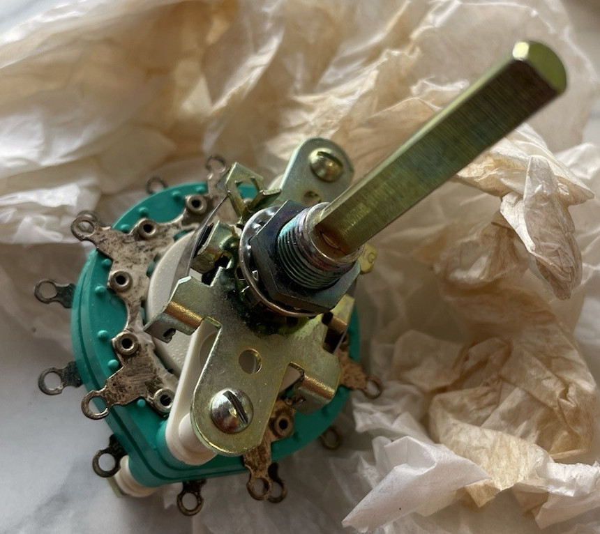
A quick browse of eBay found me a great little rotary switch to select the capacitances:
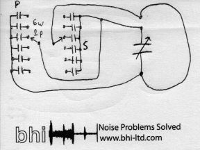
Then a rough plan was hastily scratched on a pad acquired from the National Hamfest that week (thanks Graham at BHI!):
Capacitor Selection
Of course shoving any old values in won't work, we need to scale the range of the variable capacitor $C_V$ with series capacitance $C_S$, and offset it with a parallel capacitance $C_P$. There are a limited number of discrete values that can be sourced, so the trick is to find a pair of $C_S$ and $C_P$ such that the entire range of required capacitance is covered, but with a minimal excess on either side.
For a given pair of $C_S$ and $C_P$ we need to calculate the minimum and maximum $C$ we will get with at its extremes, i.e. $C_V = 10\text{pF}$ and $C_V = 150\text{pF}$.
I wrote a script that calculates the ideal values for $C_P$ and $C_S$ from standard values and tries to minimize the mean-squared error away from the target capacitance range, which gave me these values:
| Band | Target | $C_P$ | $C_S$ | Actual | $\degree/\text{pF}$ |
|---|---|---|---|---|---|
| 30m | 93-95pF | 120pF | 180pF | 75-108pF | $11\degree$ |
| 20m | 42-46pF | 68pF | 68pF | 36-51pF | $23\degree$ |
| 17m | 23-24pF | 47pF | 33pF | 21-28pF | $49\degree$ |
| 15m | 14-16pF | 22pF | 22pF | 13-20pF | $56\degree$ |
| 12m | 8-9pF | 12pF | 12pF | 7-11pF | $105\degree$ |
As this arrangement makes it much easier to get capacitances below $10\text{pF}$, I can add the 12m band. 10m looks disappointingly out of reach. Although there are 6 spaces on the switch, I am going to populate 5 and have one with no capacitances on it at all (series short and parallel open), which allows me to use $C_V$ only.
Reality Bites
 I excitedly put this all together on a Friday evening just before a [DDRC](https://dunstabledownsradioclub.org/) meeting, and proudly strolled in to the club later on pleased to show off my creation... However it didn't _quite_ work as expected.
 Tests showed that all the ranges were there, but at lower frequencies than they should be. For example, the 30m band setting was 8.2-9.5MHz, and 20m was 11.5-13.37MHz.
It turns out that I'd failed to account for extra capacitance introduced by the rotary switch, wires, and other gubbins in the box, and that was throwing everything off.
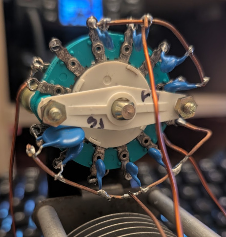
Experimental Selection
After considerable fiddling I found the following values for each of the ranges:
| Band | $C_P$ | $C_S$ |
|---|---|---|
| 30m | 68pF | 220pF |
| 20m | 33pF | 68pF |
| 17m | 12pF | 33pF |
| 15m | 12pF | 12pF |
| 12m | - | 10pF |
These values are fairly close to the original selections, and compensate for the added capacitance added by the wires and rotary switch.
Performance
Performance seems just as good as the original loop, with the added benefit that it is far easier to tune with the additional capacitances. Previously it would take a few minutes switching between the NanoVNA and the radio and carefully wiggling the capacitor shaft to get it tuned. With the band selection capacitors I can sweep the band and find a sweet spot in about a minute.
Fine tuning depends on the band, with the lower bands being much sharper than higher up, but even on 30m it a lot easier.
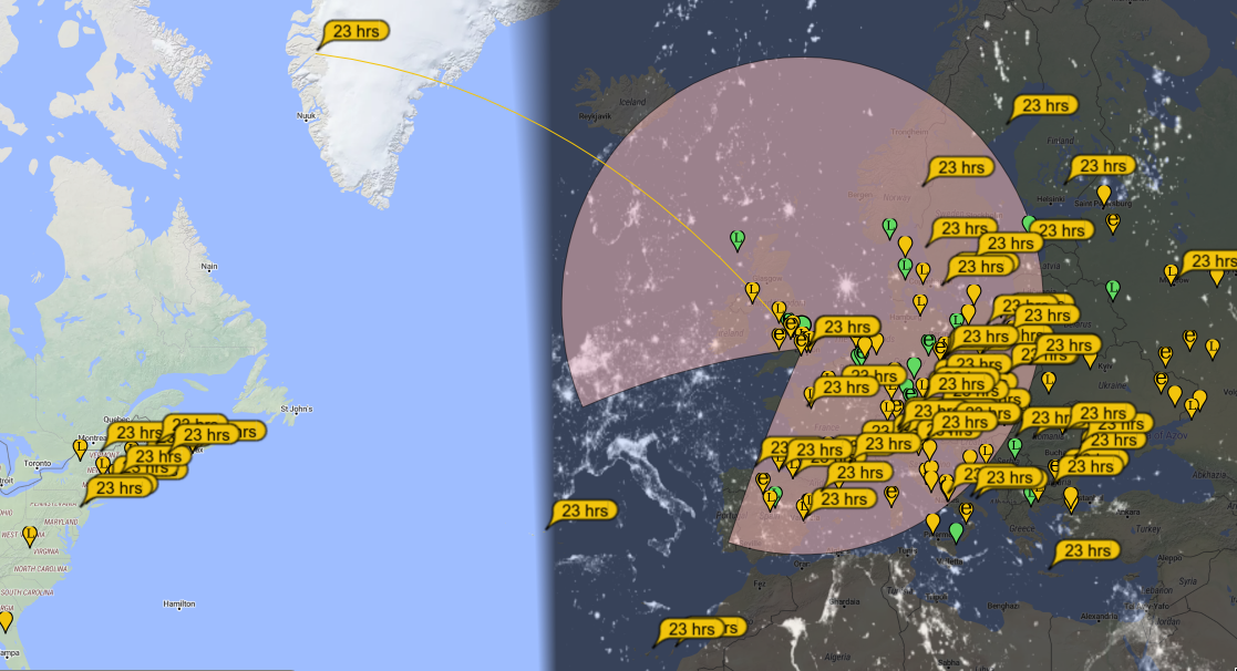
I have made contacts on both 30m and 20m with 5W of FT8. In the screenshot above I was running 5W from the VARC Cabin and was being heard in the US!
The higher bands seem to work as well, and with Reverse Beacon Network spots on 17m, 15m, and 12m, although no contacts yet.
Overall I'm very happy with v2 of the loop, the only remaining niggle is the box which I need to spend some time designing to be a bit more rugged and "suitcase-proof" than the open frame, if it is to meet the original brief for a travel friendly design.