We recently returned from a holiday in Devon, which was a great opportunity to try out some of my portable antennas. I used a 40m End Fed Half Wave at the lodge, and a 5.6m Chinese telescopic whip (affectionately known as "14 vibes" due to he poorly translated marketing material) while out and about. Both of these worked well as they have done for a number of POTA activations.
One of the minor annoyances with both of these is the required footprint. The EFHW needs a 20m linear space, and the vertical needs radials. This lead me to thinking about Magnetic Loops due to their much smaller size.
I ran across Mario G8ODE's excellent report about building 30m-15m Magloop with 3m RG213.
A root around in the garage turned up an offcut of RG213 that was just over 4.2m long. This should be enough to build a loop that performs a little better on 30/20, and perhaps let me work 40m too.
Loop Size
Plugging the loop length and conductor diameter in to Miguel VK3CPU's brilliant calculator allowed me to evaluate various configurations of the loop and find out the required capacitance and efficiency. The numbers below are with a 10mm O/D conductor, which is roughly the size of the RG213.
G8ODE's 3m loop
| Band | 40m | 30m | 20m | 17m | 15m |
|---|---|---|---|---|---|
| Capacitance | 169pF | 80pF | 37pF | 19pF | 12pF |
| Efficiency | 7% | 21% | 46% | 67% | 78% |
G8ODE reported that his 3m loop worked well on 15m but performance fell below 20m which matches the numbers from the VK3CPU calculator.
3.5m Loop
| Band | 40m | 30m | 20m | 17m | 15m |
|---|---|---|---|---|---|
| Capacitance | 138pF | 64pF | 28pF | 13pF | 7pF |
| Efficiency | 11% | 30% | 58% | 76% | 85% |
An extra 50cm seems to improve the 20m performance by quite a bit, however this is at the expense of losing 15m due to the small capacitance required for a match. The 12pF required for the 3m loop is rather small, and the larger loop size means this goes even lower with the 3.5m loop which could be a problem depending on the capacitor we use.
4m Loop
| Band | 40m | 30m | 20m | 17m | 15m |
|---|---|---|---|---|---|
| Capacitance | 115pF | 52pF | 21pF | 9pF | 3pF |
| Efficiency | 16% | 39% | 67% | 83% | 89% |
A 4m loop would be slightly smaller than 0.1λ @ 40m so the performance there is not a great deal better. 30m becomes a bit more workable, and 20m is much improved. With this loop at 17m the required capacitance of 9pF is likely to be too small for our variable capacitor. In totality the extra 0.5m doesn't pay off.
Capacitors
It was at this point I read somewhere that it is best to start with the capacitor and work backwards from there. Fortunately I was able to find a 150pF variable capacitor. The one pictured came from eBay which was around £15, I've since bought a few more from radio rallies for between £5 and £10.
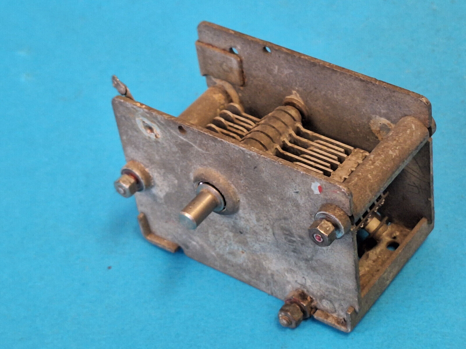
This particular capacitor was taken from a transmitter. The key thing to look for is ~1mm separation between the plates, since magnetic loops can generate quite high voltages even with low power levels, and we want to prevent arcing between the plates.
Measuring small capacitances can be tricky and it is important to measure your test setup first to get a baseline reading, which in my case is about 13pF.
| Reading | Less offset | |
|---|---|---|
| Min | 23pF | 10pF |
| Max | 163pF | 150pF |
Rather pleasingly my measurements matched the seller's exactly. I think I got lucky with the minimum capacitance which from looking at similar devices I had expected to be closer to 30pF. This gives me two options:
- Select the 3m loop and sacrifice efficiency on 20m in exchange for coverage on 15m, no possibility of a tune on 40m
- Select the 3.5m loop and get more efficiency on 20m, lose the ability to cover 15m, get very low efficiency coverage on 40m.
For the first version of the loop I will play it safe and go with 3m. The larger loop doesn't give me the efficiency that I would like on the other bands. I can add capacitance later or play with the loop size once I get something working and have a feel for how well it works.
Construction
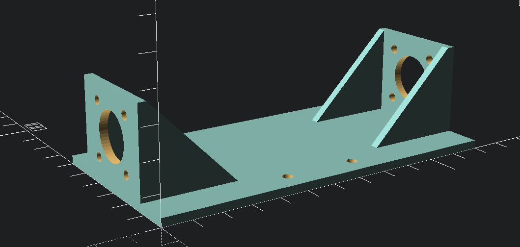
I whipped up a bracket in OpenSCAD to mount the capacitor and SO-239 sockets. This was printed in PETG with a thickness of 2.8mm and a 50% infill which makes it nice and rigid. This may need a revision to allow mounting to a pole.
I then mounted the capacitor to this, and in turn a metal bracket to attach it to a wooden baton. A small knob makes it slightly easier to adjust (the extension proved to be too long and will be removed!).
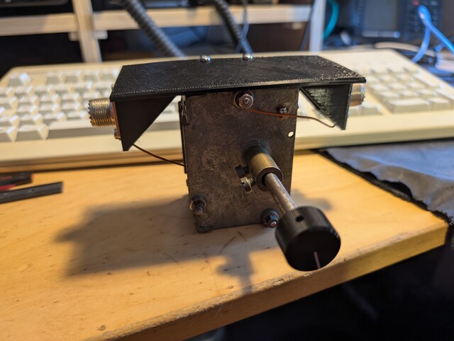
I was then able to attach all of this to an old camera tripod.
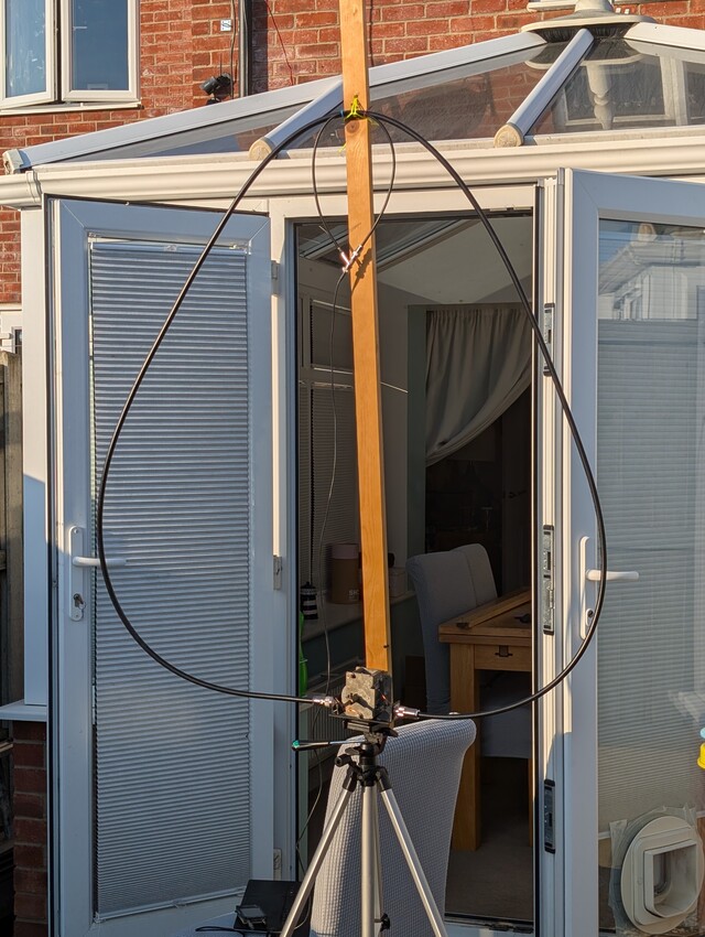
I didn't add a cross piece at first so the shape became more egg-like, however this didn't seem to stop it from working.
The inner loop was made of $\approx$ 60cm RG58 with the inner at one end connected to the shield at the other, as per G8ODE's design.
Testing
Tuning was rather tricky. I was able to get pretty close with a NanoVNA, but needed small adjustments once the Icom 705 was connected, possibly due to some interaction from standing close to the loop.
It had a very sharp dip which I was able to move to the 20m band. The tune was VERY sharp and difficult to get to a given frequency, as the bandwidth was around 10kHz. I found that changing the length of the inner loop by a few cm did not appear to make much of a difference, however the shape did seem to affect the tune and bandwidth.
Once tuned on 20m it seemed rather effective. Prevailing HF conditions were good but even so I was surprised to be heard in the USA with 5W of FT8.
A second stab up at the VARC Cabin proved that I could get a good tune on the 17m and 15m bands as well, with a number of Brazilian stations booming in. Sadly I wasn't successful in working them.
Conclusion
I'm pleased with this initial attempt and pleasantly surprised at how quickly it came together. I've got a few different improvements to make and directions to explore:
- Improve Faraday/feeding loop, if nothing else to make it more robust (by the time I wrote this it had fallen apart).
- Improve frame - Greg M0YGL suggested 20mm conduit and some 3D printed pieces so it could be packed away easily.
- Make tuning easier - a reduction drive would be a great help. Possibly also look at a motorized drive.
- Different loop sizes, configurations, multiple turns.
I plan to continue experimenting with this loop and in the short term work towards a portable solution for future holidays. There are enough branches that this should keep me occupied for a while :)