Some of my friends over at VARC have been experimenting with the 8m band, which appears to have some interesting properties. So far the station is receiving only on 40.68MHz while we wait for a licence to transmit.
The plan is to do some initial testing at QRP power levels, using a uSDX clone. The site where this is hosted happens to be only a few miles from Luton Airport, and 3rd order harmonics for 40MHz end up slap bang in the middle of the airband, so we need to be very careful not to do anything that will upset the CAA!
Filter Design
As we are starting with only low power, I decided to have a go at putting together a simple low pass filter. The topography I chose was the Chebyshev Pi as it is simple to implement, and can perform well with minimal components.
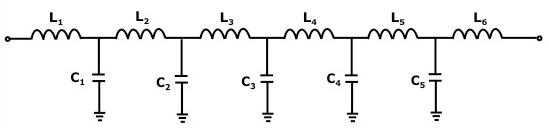
I calculated the component values with this Chebyshev Pi LC Low Pass Filter Calculator with the following parameters:
- Cutoff Frequency: 45MHz
- Impeadance Z0: 50Ω
- Frequency Response Ripple: 1dB
- Number of Components: 7
This yielded values of:
- C1,C4 = 153pF
- C2,C3 = 218pF
- L1, L3 = 196nH
- L2 = 207nH
The capacitor values are pleasingly close to 150pF and 220pF which I had in stock. Not the case for the inductors. Fortunately I have a lot of enamelled copper wire!
Inductor Winding
In the past my efforts to construct inductors have not been fruitful. Usually I'd start with researching the exact dimensions, wire diameter, and number of turns for the wanted value, then carefully perform the winding, only to test the result and find it was way off, lose interest and abandon the project.
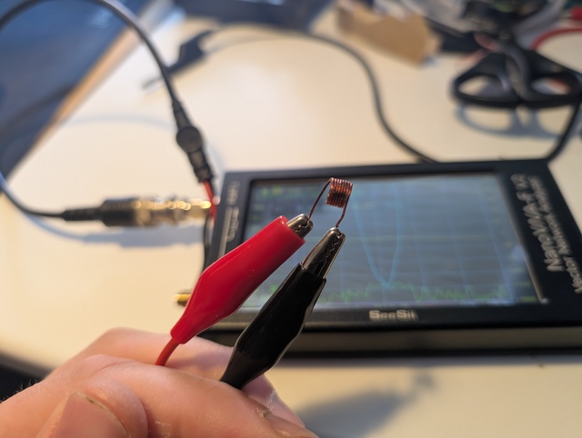
This time I decided to adopt a more experimental approach: I found an M4 bolt ($\approx$5.5mm diameter) in my junk box, wound some wire around it and measured it with my NanoVNA. The goal was to get to about 200nH, which would then be further adjusted to get closer to the value that I needed.
It is also worth noting that Chebyshev filters are quite tolerant to variances in component values, and getting more or less 200nH for each inductor would be sufficient.
I was able to get a range for a number of turns by winding the first coil around the M4 screw thread, the compressing the coil to make it shorter and increase the inductance slightly. The 'compressed' coils were held in place with a dab of superglue.
| Turns | Length | Inductance |
|---|---|---|
| 5 | 6.5mm | 85nH |
| 5 | 4mm | 130nH |
| 8 | 10mm | 160nH |
| 8 | 6mm | 210nH |
| 7 | 10mm | 150nH |
| 7 | 5mm | 200nH |
The magic number seemed to be 7 or 8 turns, compressed and held in place with glue.
Construction and Testing
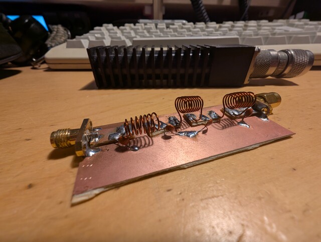
Since trying it for the first time a few months ago I've become a big fan of Manhattan style construction. The first version of the filter went together easily, however when tested with the NanoVNA the cutoff was slightly too low.
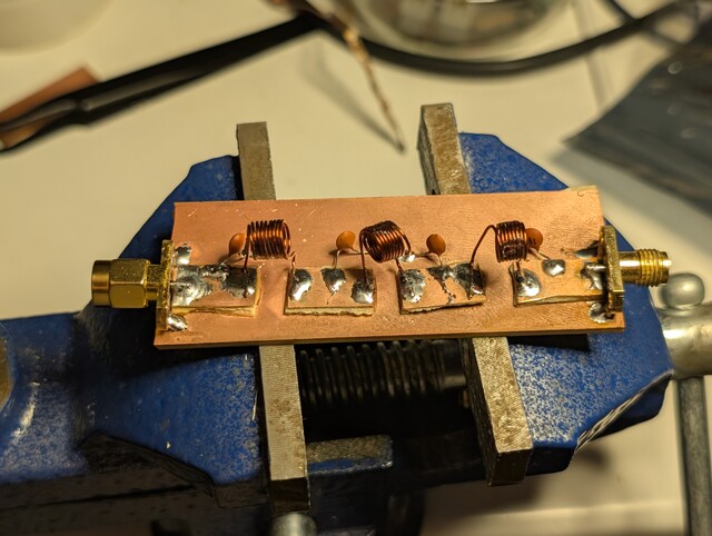
As the capacitors were standard values I expected that the inductance in circuit was maybe slightly higher than anticipated, so I re-wound the coils with 7 turns but this time did not compress and glue them. This would allow me to make small adjustments in place.
The final result was:
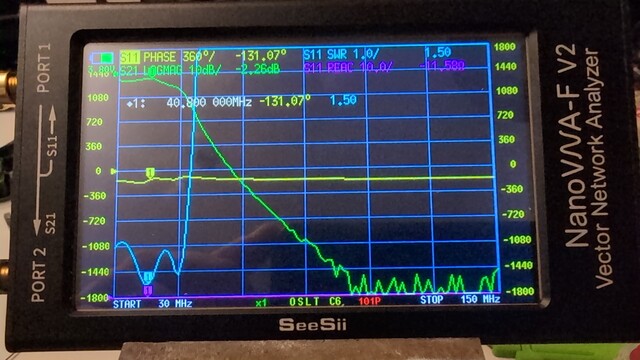
This shows an OK SWR, with 2.2dB insertion loss, slightly higher than I would like. It should suffice for our initial tests.
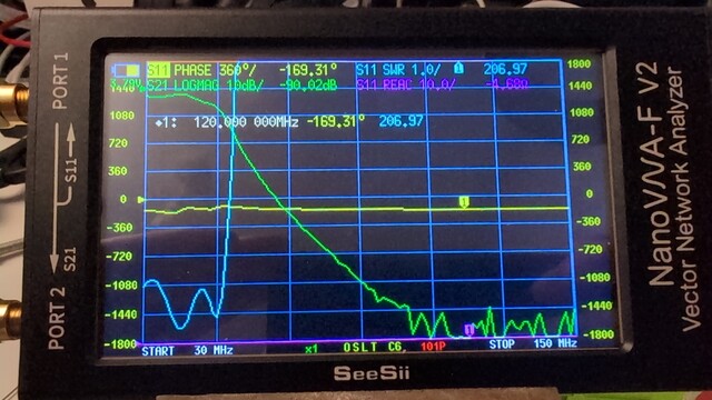
At 120MHz we see -90dB gain(!) which should be ample to keep us from upsetting the airport folks.
Power Rating
I believe the ceramic capacitors are rated at 50V. If we derate by 50% and apply $P = \frac{V^2}{R}$ which gives us $\frac{25^2}{50} = 12.5\text{W}$ as a ballpark figure. With the uSDX the power won't exceed 5W.
The copper wire used for the inductors is 0.5mm in diameter, according to this wire gauge chart the maximum current load rating is 3.5A for a single core. At 12.5W the RF currents will be well below this, so our power rating is 12.5W maximum.
Conclusion
This was my first successful filter design project and a fun way to spend an evening. The inductors came together much better than expected and I am glad that I tried a different approach (i.e. just wingin' it).
The transmit licence for the club will be up to 100W so I am expecting to rebuild this at a later date with bigger caps (> 100V rated), heavier gauge wire (> 1mm diameter) for the inductors, and housed in a sturdy metal box to keep the RF contained.